About Reverse Lockout Setup
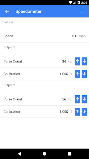
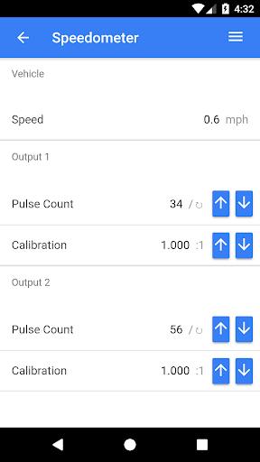
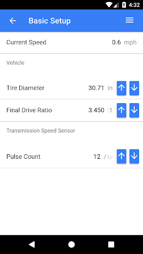
The Bowler all-in-one utilizes a small, built in, epoxy sealed box that will control each of the 3 functions with power and grounding for each function through a switched +12v circuit and a wire connected to the negative battery post or engine block. Control of the reverse lockout solenoid is based on a user defined speed setting (Default is set at locked above 4 MPH and unlocked at 0-3 MPH) This eliminates the need for a separate lock out control box which is currently the only option to activate the reverse lock out correctly. Currently most folks just simply connect their lock out solenoid to a momentary on/off switch such as the brake light switch to activate. This method will get the job done, but can over work the solenoid, and over time shorten its life span. For your electronic speedometer, the harness is equipped with 2 speed sensor outputs; the speed sensor outputs generate a square wave signal that goes from about -5 to roughly +5 volts, varying in frequency as the speed changes. But, you say, my ECM input needs a positive only signal! No problem! The output will automatically shift and give you 0 to +10 volts. The 2 speed sensor outputs are completely independent and can be calibrated separately with any pulse count and ratio you want. So, these two outputs should pretty much be able to drive any common speedometer, cruise control, or ECM. This will give you much greater flexibility in the components you are able to use and requires less time wiring everything up. The reverse lights are powered by a single output wire connected to the positive side of your reverse lights; grounding of those lights should be local to the bulb socket.
Additional App Information
-
Category:
-
Latest Version:3.0.7
-
Released on:Aug 22, 2017
-
Developed by:Bowler Performance Transmissions
-
Requires Android:Android 7.0+
-
Available on:
-
Report:
